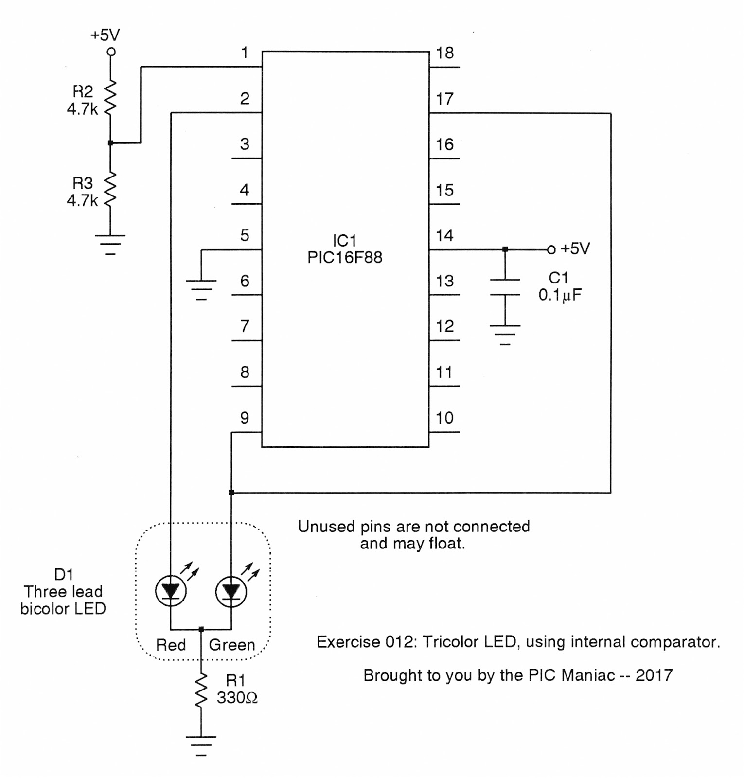
In the previous exercise we saw an external transistor used as an inverter to create the pulse train driving the green element of a three-legged bi-color LED. Here we'll drive the green element directly, and then use one of the PIC16F88's internal comparators as an inverter to drive the red element. Once again, we see that the two elements are controlled by complementary pulse trains.
Resistors R2 and R3 set a midpoint threshold for the internal comparator, and then this is driven by the PWM output at pin 9. Finally, the output of the comparator connects to the red element of the three-legged bi-color LED. Once more, we're able to attain shades of color ranging from red to orange to green.
Be sure to check out the source code as well as the PIC16F88 datasheet to learn how the versatile comparator within the chip is configured.
Click to get the source code.
Click to get the schematic PDF.
Next project:
RGB LED

No comments:
Post a Comment